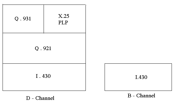
The three protocol layers for the D Channel are
ISDN has a three layered protocol architecture defined for the D channel. Whereas for the B Channel, only Physical layer is defined (I.430) and the rest of the upper layers are dependant on the application.

The three protocol layers for the D Channel are
Layer 2 D channel protocol is called LAPD (or Q.921) and it defines the procedures for ensuring error-free communication over the physical link. It defines the logical connection between the user and the network. The protocol also provides rules for multiplexing multiple TEs on a single physical channel (multi-point) on the BRI environment.
Layer 3
D channel protocol (Q.931) defines the signalling and call control messages
used to request from the services. These messages are carried in the Information
fields of LAPD frames, which are transmitted bit by bit across the physical
link.
The layer 2 and layer 3 protocols define the logical link and signalling
protocols, respectively, between ISDN TE (TE1 or TA) or customer
premises switching equipment (NT2), and the LE. The NT1 provides only a
layer 1 service and , therefore, layers 2 and layers 3 are transparent
to it. It is important to note that the layer 2 and layer 3 protocols are
specified only on the D channel. The user may choose any protocol
for the bearer services and teleservices on the B or H channels. All channels
share the same Physical layer standard since B, H and D channels are time
division multiplexed on the same physical line.