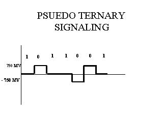
The BRI line coding scheme is called pseudo-ternay signaling. In pseudo-ternary signaling, a 0 bit is represented by a line signal of approximately 750 millivolts (mV) that alternates between positive and negative polarity. A 1 bit is represented by the absence of line voltage.

In pseudo-ternary signaling, two consecutive 0-bit pulses with the same polarity form a bipolar violation. These violations are not necessarily errors; they are used on the BRI to provide transmission synchronization information.
Frames
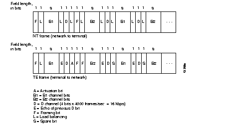
Transmissions on the BRI are organized into blocks of bits called frames, with each frame containing 48 bits.

The above figure shows the I.430 frame format. Four thousand frames
are transmitted every second, yielding the BRI bit rate of 192 kbps. Each
frame contains 16 bits from each of the two B-channels and 4 bits from
the D-channel yielding data rate of 64 and 16 kpbs, respectively.
The interleaving scheme of the B- and D- channel bits one frame on the
BRI is:
| Channel: | B1 | D | B2 | D | B1 | D | B2 | D |
| No.of bits | 8 | 1 | 8 | 1 | 8 | 1 | 8 | 1 |
The beginning of the frame sent from the TE to the NT are offset by
two bit times from the beginning of the frames sent from the NT to the
TE. In this way NT drives the timing for all TEs.
All TE's in the point-to-multipoint configuration must be able to share the B and D channels. Since more than one TE is never assigned to a B channel, there will never be more than one TE transmitting during any B-channel bit time. Even when multiple TEs transmit simultaneously on the D channel, there will never be any destroyed bits or other signaling ambiguities because:
Frames sent in the two directions are basically the
same, with a notable exception being that the NT-to-TE frames carry the
echoedD channel bit (E-bits), which merely repeat the bits that were transmitted
on the D-channel in the TE-to-NT direction. The E-bits are of particular
importance in the point-to-multipoint configuration. Since there may be
multiple TEs on the BRI line, some mechanism must be in place to ensure
that only a single TE is transmitting on the D-channel in the TE-to-NT
direction at any given time.
Pseudo-ternary signaling voltage and the electrical attachment of TEs to the BRI line are designed in such a way that if two TEs transmit simultaneously on the D channel, and one sends a 0 and the other a 1, the 0 will be detected by the NT and returned as an E-bit. This occurs because of the fact that a 0 is represented by the presence of a line voltage and a 1 by the absence of any line voltage. Thus a TE that transmits a 0 will always detect an E-bit with a 0 value, while a TE that transmits a 1 may hear either a 0 or 1 back on the E-bit. Every TE compares the D channel bit that it had sent in the previous frame with the E bit received in the next frame sent by the NT. If both of these are the same, then the TE continues transmitting on the D channel. Otherwise, it backs off and waits for the D channel to become idle. Thus it can be seen that finally only one TE will completely transmit its frame and all the other TE's would have backed off.
Mutltiframe
The BRI specification also defines multiframes, a grouping together
of 20 I.430 frames. The Multiframing (M) and Auxiliary Framing (Fa) bits
are used in the multiframing procedures. See the following table.
I.430 Multiframing.
| Frame No. | TE-to-NT
Fa |
NT-to-TE
Fa |
NT-to-TE
M |
| 1 | Q1 | 1 | 1 |
| 2 | 0 | 0 | 0 |
| 3 | 0 | 0 | 0 |
| 4 | 0 | 0 | 0 |
| 5 | 0 | 0 | 0 |
| 6 | Q2 | 1 | 0 |
| 7 | 0 | 0 | 0 |
| 8 | 0 | 0 | 0 |
| 9 | 0 | 0 | 0 |
| 10 | 0 | 0 | 0 |
| 11 | Q3 | 1 | 0 |
| 12 | 0 | 0 | 0 |
| 13 | 0 | 0 | 0 |
| 14 | 0 | 0 | 0 |
| 15 | 0 | 0 | 0 |
| 16 | Q4 | 1 | 0 |
| 17 | 0 | 0 | 0 |
| 18 | 0 | 0 | 0 |
| 19 | 0 | 0 | 0 |
| 20 | 0 | 0 | 0 |
The M-bit (only present in the NT toTE direction) is set to 1 in the first frame of each multiframe and is set to 0 in all other frames. Each multiframe in the TE-to-NT direction contains four Q-channel bits, designated Q1, Q2, Q3 and Q4. The four Q-channel bits occupy the Fa bit position in every fifth frame. In those frames not carrying Q-channel information, the Fa -bit is set to 0. In the NT-to-TE direction, the Fa-bit indicates frames in with Q-Channel information should appear. Thus, the Fa-bit is set to 1 in every fifth frame and set to 0 in the other frames. Multiframes provide an 800-bps Q-channel in the TE-to-NT direction. Currently the Q channel is not used for any purpose and is reserved for future use.
In the TE-to-NT direction, the Fa-bit is set to 0 in those frames not carrying Q-Channel bits. Therefore, a second bipolar violation will occur within 13 bit times of the beginning of the frame in four out of five frames. This ensures that the TE is able to periodically synchronise its clock with that of the LE.
The Activation(A) bit is used to indicate that the BRI line is
activated and sending real user data; its use is part of the activation
procedure of the physical interface. This bit is sent only in frames sent
in the NT to TE direction.